
Reactive current compensations
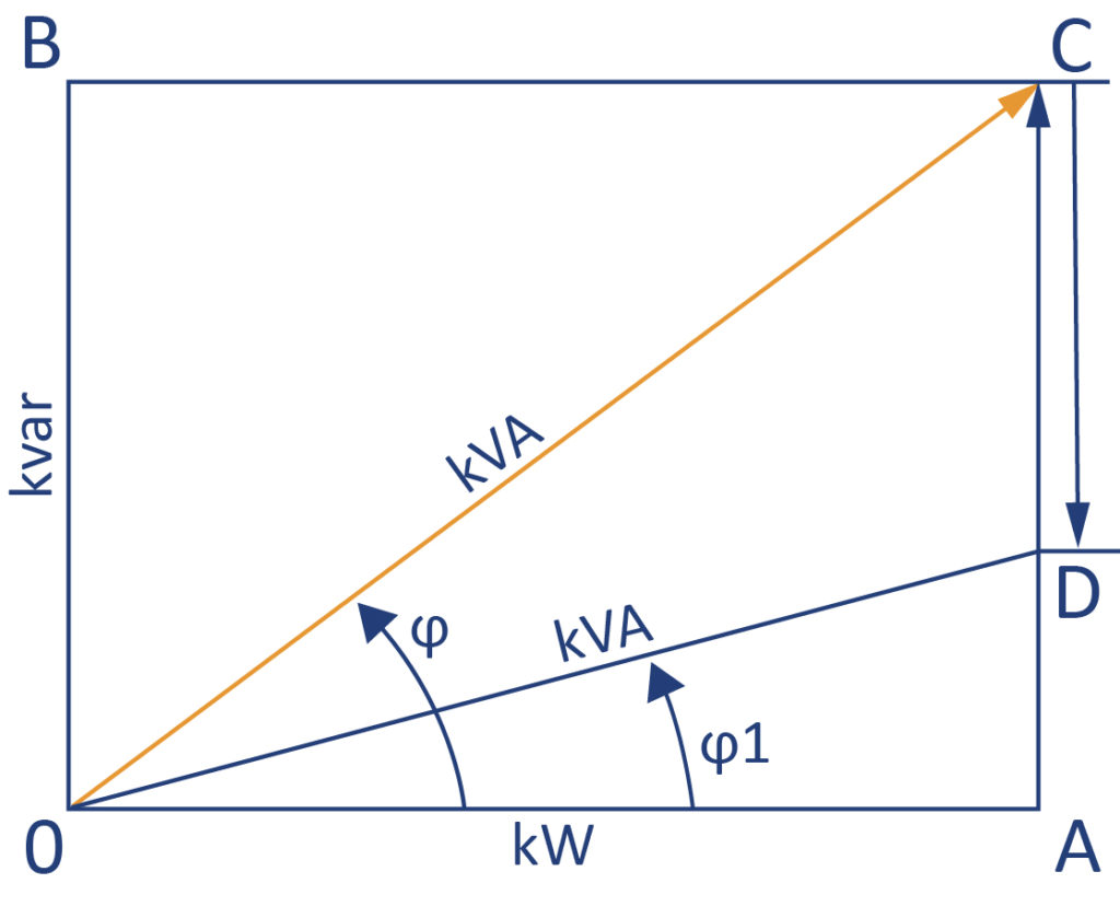
0A = Active power (kW)
0B = inductive reactive power (kvar)
0C = Apparent power (kVA)
CD = Capacitor reactive power or capacitive reactive power
φ = Phase angle, uncompensated
φ1 = Phase angle, compensated
0A ÷ 0C = Power factor cos φ
0D = compensated power
Compensate inductive reactive power
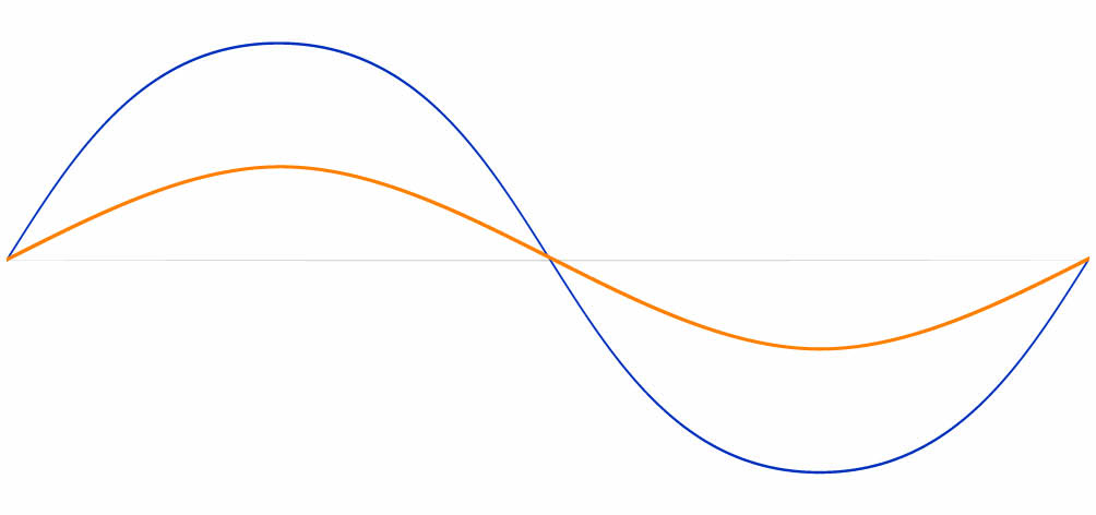
Inductive current consumers, i.e. motors, transformers, welding machines, choke coils and the like, as well as converters for controlled drives, require so-called inductive reactive energy (kvarh kilovar hours) to build up the magnetic fields or for control and commutation. This energy is not converted into mechanical work or heat by the apparatus like active energy (kWh kilowatt hours), but it oscillates back and forth between the generator and the consumer. The active energy and reactive energy are registered at the electricity consumers with different meters, i.e. active energy with kilowatt-hour meter and the reactive energy with kilovar-hour meter. The magnetizing reactive current is the cause of various adverse phenomena. It stresses the transmission lines, transformers and generators, it causes additional current heat losses and voltage drops, and it requires stronger dimensioning of all transmission elements. By installing static capacitors, the reactive current transport from the generator to the consumer can be largely reduced or compensated. A power factor (cos φ) is coupled to the electricity supply contracts between the energy consumer (predominantly commercial companies) and the energy supplier in order to pass on the excess reactive power to the consumer by means of the data recorded in the kilovar hour meter. In this way, the energy supplier primarily does not want to charge its customer high reactive power costs, due to the transmission lines and transformers loaded with reactive current, but instead wants to create an incentive to compensate for their reactive power requirements by installing power capacitors for the purpose. Both sides benefit from this, because the current relief allows a saving in plant costs or a better utilization of the existing plants. The reduction of the current heat losses results in a considerable reduction of the permanent costs for generation and transport of the energy. Thus, generators, transformers and transmission lines can be dimensioned smaller with optimal active current utilization. Unnecessary capital investments for larger machines and lines are saved. In order to efficiently compensate for the required inductive reactive power, you can access our tools and solutions via the following links.
Our tip: Regularly check the invoice you receive from your grid operator for reactive power costs. If these are incurred … we are here to help and advise you:

Compensate capacitive reactive power
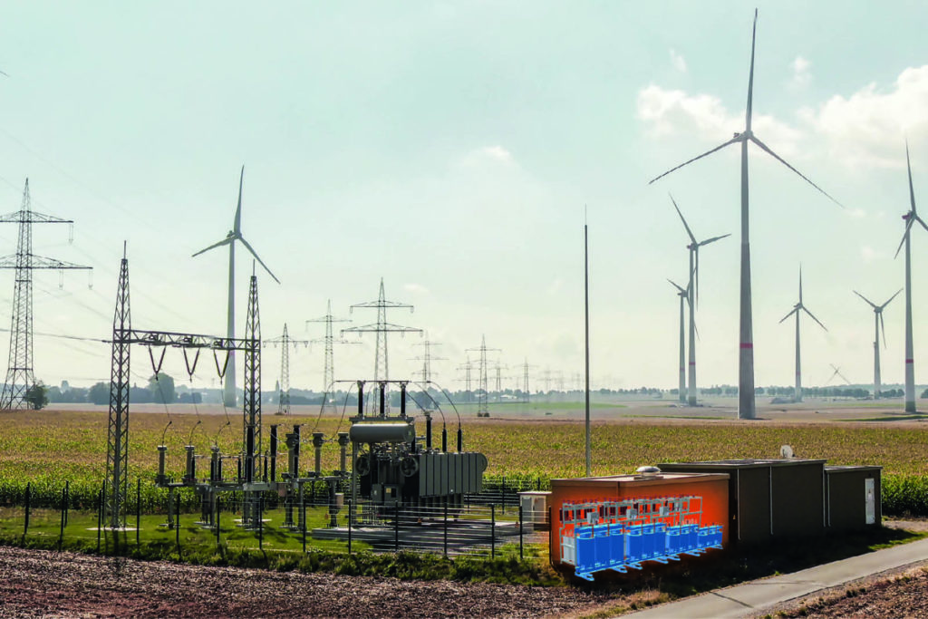
If we imagine that the inductive reactive power described above is the ‘yin’ in reactive current compensation, then the compensating ‘yang’ is still missing: the capacitive reactive power. This is because, especially in no-load operation, input filters of converters or cable networks exhibit a clearly capacitive behavior. In total, this can result in a capacitive reactive power of several 100 kvar for a wind or photovoltaic farm, for example – due to the amount of cables installed. However, this capacitive reactive power is generally not desired by the grid operators and, like inductive reactive power, results in high reactive power costs for the consumer. For this reason, it is essential – e.g. when operating wind and solar farms that have a high capacitive characteristic during no-load operation – to effectively counterbalance this with an inductive compensation system. On the one hand, the limit values for the capacitive reactive current demand are part of contracts between grid operator and consumer … on the other hand, inductive counter-compensating reactive power systems are generally required at the grid node even before commissioning of a renewable energy park – due to technical connection rules and relevant standards. In order to efficiently compensate for capacitive reactive power, e.g. in low-load operation of photovoltaic parks, Condensator Dominit has specifically included the INKA product group in its product portfolio for low- and high-voltage grids.
Please observe the technical connection rules and specifications of the grid operator already in the project planning phase of a new renewable energy park to be developed, in order to feed in the generated energy at the grid node in accordance with the standards with the help of our INKA and MIKA systems: